Real-Time 6-DoF Pose Estimation by an Event-Based Camera Using Active LED Markers
Unique LED blinking frequencies establish identities between event pixels and known marker geometry. Short-window accumulation detects LEDs and their frequencies; independent trackers update subpixel LED centers per event, and IPPE-PnP asynchronously outputs marker 6-DoF pose relative to the event camera. Desktop tracking averages 354 μs latency at 3.81 kHz. Static experiments at 2.1–4.8 m give mean errors of 34.5 mm / 0.738°, with demonstrations of approximately 10 m/s drone flight. Performance depends on active hardware, bias tuning, full LED visibility, and planar PnP geometry. Outdoor high-speed experiments do not establish preservation of static accuracy.
asynchronous event streamactive LED marker with frequency-coded pointsknown planar marker geometry
Requirements
calibrated event cameraactive LED hardware and stable blink frequenciesknown 3D LED coordinates and marker identitiessensor-specific bias tuningcomplete visibility of all tracked LEDs
Full paper metadataAuthors, affiliations, research area, datasets, metrics, method tags, and reading statusExpandCollapse
Authors
Gerald Ebmer, Adam Loch, Minh Nhat Vu, Roberto Mecca, Germain Haessig, Christian Hartl-Nesic, Markus Vincze, Andreas Kugi
Affiliations
TU Wien / Austrian Institute of Technology / Prophesee
calibrated event cameraactive LED hardware and stable blink frequenciesknown 3D LED coordinates and marker identitiessensor-specific bias tuningcomplete visibility of all tracked LEDs
Reading Notes
Overview / Deep Dive
Available src/paper-notes/event-led-pose-wacv2024/coarse.md
Paper overview notes
Quickly assess the paper's scope, problem setting, core method, experimental findings, and whether to read it in depth.
Overview Notes: Real-Time 6-DoF Pose Estimation by an Event-Based Camera Using Active LED Markers
1. Basic information
Authors: Gerald Ebmer, Adam Loch, Minh Nhat Vu, Roberto Mecca, Germain Haessig, Christian Hartl-Nesic, Markus Vincze, Andreas Kugi
Affiliations: TU Wien Automation and Control Institute, Austrian Institute of Technology, Prophesee
The paper combines microsecond event-camera timestamps with known LED blink frequencies to establish identifiable 2D–3D correspondences. A detection thread finds and identifies LEDs, a low-latency tracking thread updates centers per event, and asynchronous IPPE-PnP estimates marker-board pose relative to the camera. Desktop performance reaches 354 μs mean tracking latency and 3.81 kHz output, requiring active LEDs, known frequencies and geometry, carefully tuned sensor biases, and suspension of pose output if any LED is occluded.
3. Task boundaries
Item
Actual paper setting
Target
Active LED marker / marker board, rather than natural object appearance
Inputs
Prophesee events, camera intrinsics, LED frequencies, and known 3D layout
Outputs
Marker-frame rotation and translation relative to the event camera
Initialization
Automatic frequency detection; no manually supplied initial pose
Fast relative localization, drones, and reference poses for dynamic handover / pick-and-place
This is a dedicated optical localization system with high bandwidth, low latency, and redetection, rather than a general natural-object pose method in the FoundationPose / GDR-Net family.
4. Method overview
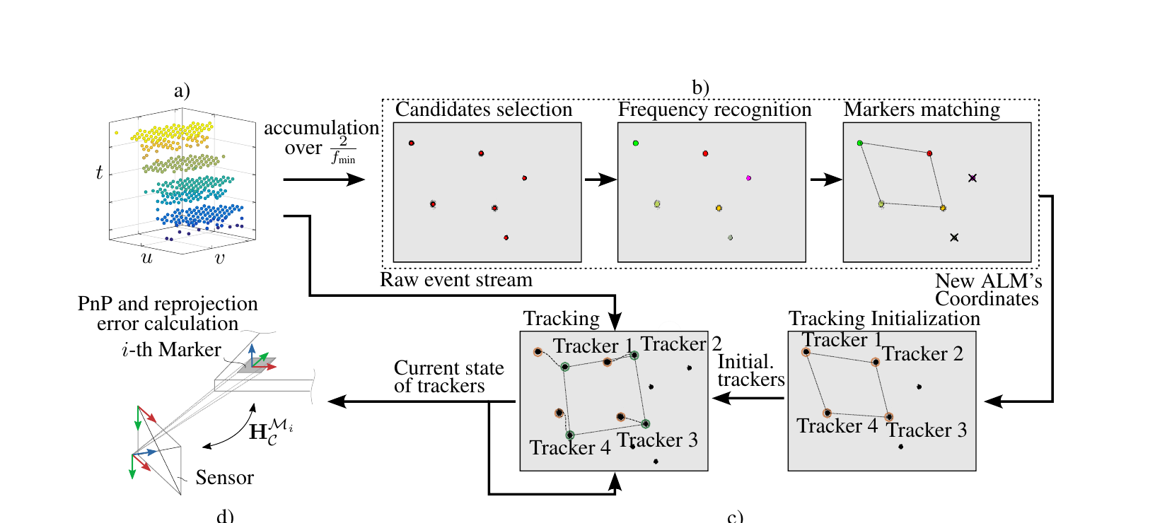
Original Figure 2: event-accumulation detection, frequency identification and marker matching, asynchronous per-LED tracking, and IPPE-PnP with reprojection checks. Source: CVF Open Access. Image copyright belongs to the paper’s authors and publisher; shown here for paper analysis.
Tune the sensor to isolate LED blinking: refractory, high-pass, low-pass, and other biases aim for one event per relevant pixel per blink while suppressing background events.
Accumulate briefly for detection: the window covers at least two periods of the lowest LED frequency. Connected components provide candidates, and inter-event interval histogram peaks identify blink frequencies.
Frequency supplies identity: unique frequencies directly associate 2D LED centers with predefined 3D marker points.
Track centers per event: after detection, each LED gets an independent tracker; low-pass center updates avoid waiting for another accumulated event frame.
Asynchronous PnP: immediately after one solve, run IPPE-PnP again with the latest centers. Excessive reprojection error declares tracking loss, and the detection thread recreates trackers.
5. Main results
5.1 Absolute accuracy with a stationary board
With OptiTrack ground truth, camera-to-marker-board distance varies from 2.1 m to 4.8 m:
Tracking translation error: mean 34.5 mm, standard deviation 16.2 mm, maximum 87.8 mm;
Tracking rotation error: mean 0.738°, standard deviation 0.146°, maximum 1.55°;
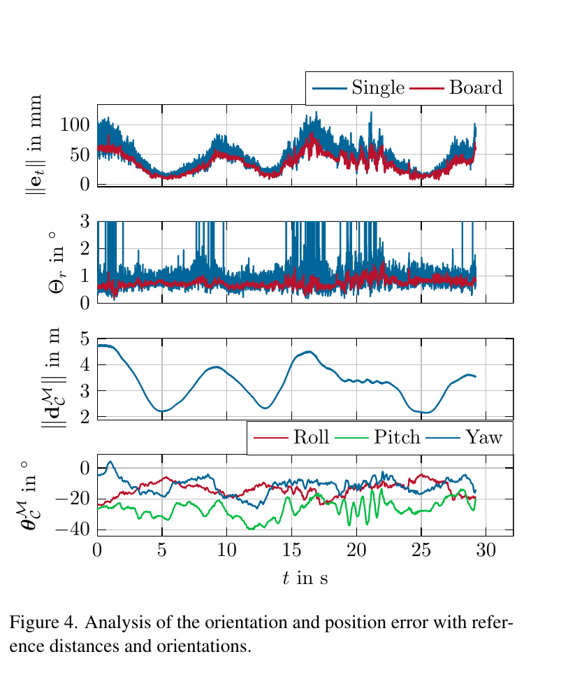
Mean translation errors are similar for a 9 cm marker and a 59 cm board, but the small marker has pronounced rotation spikes at medium / long range. A larger geometric baseline mainly improves orientation conditioning.
Original Figure 4: translation / rotation errors for a 9 cm marker and a 59 cm board over 2.1–4.8 m motion. The red board curve suppresses the small marker’s rotation spikes, while range-direction error still varies with observation geometry. Source: CVF Open Access. Image copyright belongs to the paper’s authors and publisher; shown here for paper analysis.
5.2 Latency and output rate
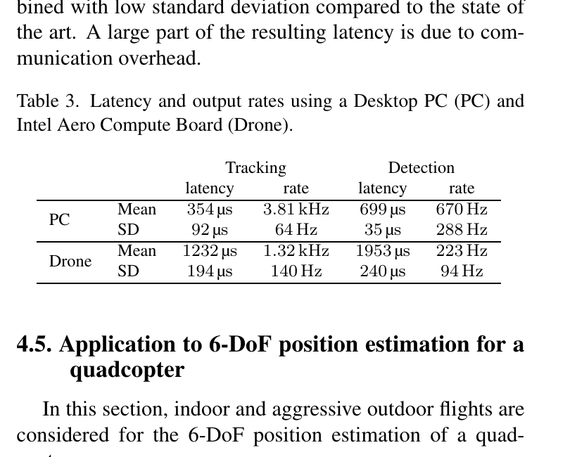
Original Table 3: desktop tracking has mean latency 354 μs and output 3.81 kHz; Intel Aero onboard tracking has 1.232 ms and 1.32 kHz. Detection is slower because it requires accumulation and frequency identification. Source: CVF Open Access. Image copyright belongs to the paper’s authors and publisher; shown here for paper analysis.
Platform / mode
Mean latency
Output rate
Desktop PC / tracking
354 μs
3.81 kHz
Desktop PC / detection
699 μs
670 Hz
Intel Aero / tracking
1.232 ms
1.32 kHz
Intel Aero / detection
1.953 ms
223 Hz
The abstract’s “below 0.5 ms, 3 kHz” refers to desktop steady-state tracking, not initial detection, onboard performance, or arbitrary event-pose systems.
5.3 Drone validation
In indoor OptiTrack experiments, active LED estimates are more stable along three translation axes than the selected ORB-SLAM2 implementation. Different sensors, priors, and computation prevent treating this as a fair general SLAM ranking.
Outdoors, a ground-mounted camera tracks motion up to approximately 4.5 m/s and altitude approximately 9 m; a drone-mounted camera moves at approximately 10 m/s on average.
The reported maximum working distance is approximately 10 m, limited by sensor resolution, lens ground sampling distance, and inverse-square attenuation of LED intensity.
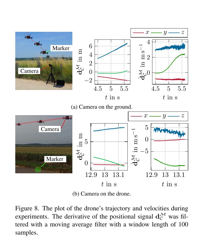
Original Figure 8: a fixed camera with drone-mounted markers, and a drone-mounted camera with fixed markers. Curves show relative position and filtered velocity. Source: CVF Open Access. Image copyright belongs to the paper’s authors and publisher; shown here for paper analysis.
6. Key limitations
Active infrastructure: targets require light-emitting markers with preregistered frequencies and 3D layouts.
Occlusion sensitivity: to preserve accuracy, the authors stop tracking when LEDs are occluded and redetect only after all LEDs become visible again.
Physical range limit: 10 m cannot be extended indefinitely by an algorithm parameter. Intensity falls with squared distance, and image resolution limits distant center accuracy.
Depth is harder: planar PnP is sensitive to z and tilt; outdoor velocity curves also show greater z noise.
Reproduction extends beyond software: camera biases, LED frequencies, drivers, clocks, lighting, and geometry calibration all matter. The source notes record no code on CVF and no accessible content at the paper’s project address when checked.
7. Assessment
The assumptions are strong for ordinary unseen objects, but the paper merits deep reading for fast robot relative localization. It integrates event formation, frequency coding, decoupled asynchronous detection / tracking, PnP conditioning, and hardware limits into an interpretable system. The 3.81 kHz operating point requires steady-state tracking, dedicated active markers, and a desktop platform; it is not an automatic pose rate supplied by event cameras.
Available src/paper-notes/event-led-pose-wacv2024/deep.md
In-depth paper notes
Support reproduction, comparison, related-work writing, and identifying opportunities for further research.
Deep Reading Notes: Real-Time 6-DoF Pose Estimation by an Event-Based Camera Using Active LED Markers
1. Positioning
This work addresses a specific robot-localization problem suited to very low latency, rather than recognition and pose estimation of arbitrary natural-image objects:
Attach active LED markers with known geometry and blink frequencies to a target; an event camera automatically detects the LEDs, continuously tracks their 2D centers, and frequently estimates marker pose relative to the camera in 6DoF.
It is event-based active-fiducial localization. Unlike AprilTag / ArUco, identity comes from each LED’s temporal frequency rather than a spatial black-and-white image code. Unlike learned event-pose methods, it trains no object network and does not regress SE(3) from event frames; explicit 2D–3D associations feed PnP.
The authors’ three main goals are:
Steady-state tracking latency below 0.5 ms;
Desktop pose output above 3 kHz;
Usable relative localization in fast, high-dynamic-range drone experiments.
Detection and tracking must be distinguished. Initial acquisition or recovery requires event accumulation and frequency identification. The strongest low-latency operating point occurs only after marker identification and LED-tracker startup.
2. Inputs, outputs, and priors
Category
Specific conditions
Sensor
Prophesee EVK4 HD, IMX636ES, 1280×720, Soyo 8 mm lens
Target infrastructure
9 cm PCB markers with 8 active LEDs each; a board of 4 markers uses the outer 8 LEDs for an approximately 59 cm geometric baseline
Known priors
LED 3D locations, unique blink frequencies, marker groups, camera intrinsics
Automated stages
Marker detection, frequency identification, 2D–3D matching, tracking initialization, and redetection after loss
Outputs
Marker-frame rotation / translation relative to the camera frame, with reprojection-based tracking status
Outside scope
Natural-object recognition, markerless pose, prolonged-occlusion inference, global camera SLAM
Strong priors make correspondence deterministic: once frequencies associate 2D LEDs with 3D points, hardware coding largely removes the difficult object-correspondence problem. The backend then updates centers and solves PnP quickly.
3. Why event cameras suit this task
An event pixel triggers when log-brightness change crosses a contrast threshold:
ek=(uk,tk,pk),ΔL(uk,tk)>pkC,
Here uk=(uk,vk) is the pixel, tk a microsecond timestamp, and pk∈{−1,+1} polarity. Frame cameras wait for exposure and readout and suffer motion blur at high speed. Active LEDs continuously create clear periodic brightness changes that match event sensing.
High temporal resolution does not automatically imply low pose latency. Accumulating tens of milliseconds of events before a heavy detector consumes that advantage. The key engineering choices are:
Accumulate only for detection, to identify frequencies;
Update centers per event during steady tracking, without full event frames;
Run PnP asynchronously, reading the newest centers immediately after each solve.
Low latency comes from jointly designing the sensor, active signal, thread decomposition, and lightweight geometry, rather than one isolated module.
4. Full pipeline
Original Figure 2: short-window candidate extraction, frequency identification, and marker matching create per-LED trackers; tracking and PnP / reprojection checks then run asynchronously. Source: CVF Open Access. Image copyright belongs to the paper’s authors and publisher; shown here for paper analysis.
4.1 Sensor biases are part of the algorithm
The authors aim for one distinct event per relevant pixel per blink while suppressing background texture, noise, and repeated triggering from the same blink. They adjust:
Refractory period: suppress immediate repeated pixel triggers after a blink;
High-pass / low-pass: shape sensor response for the LED frequency band;
Polarity: use only one polarity to reduce unnecessary events;
LED frequency: empirically above 4 kHz and below 40 kHz, favoring integer-microsecond periods to concentrate interval-histogram peaks.
Bias calibration directly controls candidate density, frequency-peak clarity, and computational load. Moving to another sensor, lens, LED driver, or outdoor lighting requires more than copying software parameters.
4.2 Detection: blobs first, identities from timing
Let the lowest LED frequency be fmin. Detection duration Td must cover at least two blinks, approximately satisfying
Td>fmin2.
Detection proceeds as follows:
Accumulate events over Td;
Select connected components with sufficient per-pixel event counts as LED candidates;
Initialize centers from the candidates’ 2D event centroids;
Histogram consecutive-event time differences, whose peaks sharpen for integer-microsecond blink periods;
Identify LEDs by frequency, group them by marker frequency sets, and establish 2D–3D identities.
Fast motion widens accumulated blobs, but covering only two periods of the lowest frequency requires less time than conventional frame exposure. Tracking further corrects centroids afterward.
4.3 Tracking: an independent low-pass state per LED
LED tracker i maintains frequency fi, 2D center cˉi, and search radius ri. When a new event uk falls inside the radius, update the center by
cˉi=β~uk+(1−β~)cˉi
the expression above, typically using β~=0.02. Every N events, reestimate the radius as twice the mean event-to-center distance.
This tracker estimates neither scale, deformation, nor an appearance template; it relies on dense periodic LED events. Per-event updates are inexpensive and yield smoothly varying subpixel centers. However, the old center and search radius form a local feedback loop that can fail under persistent incorrect events or motion beyond the radius.
4.4 Pose: IPPE-PnP, parallel loops, and reprojection gates
Frequency identities associate 2D centers ui with known 3D marker points Xi. The planar layout motivates IPPE-PnP. Pose is not solved directly for every event:
The PnP thread reads all current tracker centers;
Solve a marker-to-camera SE(3) transform;
Immediately after completion, read updated centers and solve again;
Reproject 3D LEDs with the estimated pose; if any tracker’s reprojection error exceeds the mean event-to-center distance, declare tracking lost and delete the trackers;
The background detector automatically recreates them when the complete marker is visible again.
Slow detection, fast tracking, and independent geometry resemble modern detect-then-track systems, but identity and association come from frequency coding rather than learned features.
5. Experimental setup and evidence
5.1 Hardware and ground truth
Event camera: Prophesee EVK4 HD / IMX636ES, 1280×720;
Single marker: 8 LEDs, approximately 9 cm per side;
Marker board: 4 markers arranged in a square, using the outer 8 LEDs over approximately 59 cm per side;
Ground truth: OptiTrack synchronized to the event camera by external trigger.
The paper provides dedicated hardware-system validation rather than an object-pose benchmark directly comparable with BOP methods. Metrics should be interpreted within this setup.
5.2 Absolute accuracy: tracking differs from detection
The camera moves over 2.1–4.8 m while the marker board stays fixed, with synchronized OptiTrack comparison. Key Table 1 values are:
Mode
Translation mean
Translation std.
Translation max
Rotation mean
Rotation std.
Rotation max
Tracking
34.5 mm
16.2 mm
87.8 mm
0.738°
0.146°
1.55°
Detection
64.9 mm
121 mm
1.233 m
1.55°
5.12°
71.9°
Detection has a pronounced error tail, reaching 71.9° maximum rotation error. Short-window centers and frequency identification locate markers and initialize trackers but cannot replace steady-state subpixel centers. Accuracy emphasized in the abstract and conclusion mainly concerns tracking.
Original Figure 4: blue is the 9 cm marker; red is the approximately 59 cm board. Translation errors have similar scale, but the smaller marker frequently shows medium- / long-range rotation spikes. A larger planar baseline mainly improves rotational observability. Source: CVF Open Access. Image copyright belongs to the paper’s authors and publisher; shown here for paper analysis.
Two distinctions matter:
34.5 mm is absolute translation error, not 3.45 mm;
The conclusion reports normalized position error often below approximately 1.87%. Absolute error grows with distance; near-range accuracy cannot be transferred unconditionally to 10 m.
5.3 Static noise: stability differs from absolute accuracy
In a fixed scene, translation-output standard deviation varies with distance:
Distance
Translation std.
Maximum variation
2 m
0.25 mm
2.17 mm
4 m
0.68 mm
2.95 mm
6 m
1.4 mm
5.5 mm
These values describe the noise floor around one static pose, not absolute bias relative to OptiTrack. A system can remain stably offset by several centimeters; static noise cannot replace Table 1 accuracy.
5.4 Latency and throughput: key results requiring care
Original Table 3: separate timing for tracking / detection and desktop / onboard platforms. The abstract’s “below 0.5 ms / 3 kHz” comes from Desktop PC tracking; onboard tracking still exceeds 1 kHz, with mean latency 1.232 ms. Source: CVF Open Access. Image copyright belongs to the paper’s authors and publisher; shown here for paper analysis.
Platform
Mode
Mean latency
Output rate
Intel i9-12900K
Tracking
354 μs
3.81 kHz
Intel i9-12900K
Detection
699 μs
670 Hz
Intel Aero
Tracking
1.232 ms
1.32 kHz
Intel Aero
Detection
1.953 ms
223 Hz
Latency and rate are not simple reciprocals because of concurrent threads and communication overhead. The reciprocal of desktop tracking’s 354 μs is approximately 2.82 kHz, while the table reports 3.81 kHz. Quote the authors’ synchronized-trigger measurements and output counts rather than deriving one column from the other.
Detection at 670 Hz also does not mean recognizing 670 new markers per second. This is the implementation’s detection output / processing rate; redetection still requires the physical observation window of at least two LED periods.
5.5 Indoor drone: ORB-SLAM2 comparison in system context
An Intel Aero drone performs a fast zigzag for approximately 50 s within approximately 1.8×0.6×0.4 m, with OptiTrack ground truth. Reported active-LED per-axis error bounds are approximately:
x: ±0.06 m;
y: ±0.08 m;
z: ±0.02 m.
ORB-SLAM2 has larger translation errors in the same sequence, with broadly similar orientation error but more spikes. The authors acknowledge an imperfectly fair comparison:
ORB-SLAM2 is general frame-based camera SLAM, requiring natural texture and estimating a camera trajectory;
This method knows marker identities, LED geometry, and active frequencies, estimating only relative pose between two rigid bodies;
Sensing and task priors differ.
The supported conclusion is that the dedicated ALM system is more stable than the selected ORB-SLAM2 implementation on this active-localization task, rather than general superiority over SLAM.
5.6 Outdoor drone: fast-motion visibility, without full accuracy ground truth
Original Figure 8: top, a fixed ground camera observes drone-mounted markers at up to approximately 4.5 m/s and approximately 9 m altitude; bottom, a drone-mounted camera observes fixed markers at approximately 10 m/s on average. Source: CVF Open Access. Image copyright belongs to the paper’s authors and publisher; shown here for paper analysis.
The two outdoor configurations are:
Ground-fixed camera, drone-mounted markers: maximum speed approximately 4.5 m/s and altitude up to 9 m;
Drone-mounted camera, ground-fixed markers: mean speed approximately 10 m/s.
Plotted velocities differentiate position and apply a 100-sample moving average. The experiment mainly supports detection / tracking under fast motion and long range. It lacks the unified absolute 6DoF error summary of the static OptiTrack experiment; 34.5 mm / 0.738° cannot therefore be assigned to outdoor flight at 10 m/s.
6. Evidence serving as ablations
This systems paper has no conventional deep-learning ablation table, but offers three useful variable analyses.
6.1 Default bias vs adjusted bias
Figure 3 shows that adjusted biases concentrate event-time clusters for each LED blink and reduce background events. Frequency histograms compare default, low-pass, high-pass, and adjusted settings. This supports treating sensor parameters as part of the algorithm, but supplies no automatic cross-scene tuning method.
6.2 Detection vs tracking
Tracking versus detection is the strongest system ablation: tracking improves accuracy, latency, and output rate. The difference comes from more accurate, more frequently updated centers through single-event tracking, rather than a different PnP solver.
6.3 Single marker vs marker board
Comparing a 9 cm marker with a 59 cm board reveals geometric conditioning: enlarging the point-set baseline does not reduce mean translation error by an order of magnitude, but substantially suppresses orientation spikes. This is more informative for planar PnP than one mean error.
7. Author claims and this site’s assessment
Topic
Author evidence
Site assessment
Below 0.5 ms
Desktop tracking mean 354 μs
Supported for steady-state tracking on an i9 desktop; not the detection or onboard figure
Above 3 kHz
Desktop tracking 3.81 kHz
Supported for a dedicated active-marker pose loop, not natural-object event pose
Fast motion
Outdoor experiments at approximately 4.5 m/s maximum and 10 m/s average
Supports continued observation; no comparable outdoor GT summary establishes retained 34.5 mm accuracy
10 m range
Experiments and GSD / intensity analysis
Approximate operating limit for this hardware, not an algorithmic guarantee
Better than ORB-SLAM2
Lower per-axis indoor errors on the same trajectory
Supported for the dedicated task; differing priors, sensors, and outputs prevent a general ranking
Robustness
Low static variance, dynamic tracking, and redetection
Strong with complete marker visibility; the authors stop tracking under partial LED occlusion, limiting occlusion robustness
8. Failure modes and implicit assumptions
8.1 All LEDs used for PnP must be visible
For accuracy, the paper does not track markers with occluded LEDs. Excessive reprojection error or incomplete LEDs produce a lost state; trackers are recreated only when all LEDs reappear. This can suit open outdoor high-speed scenes, but hands, grippers, or objects easily occlude markers during grasping, handover, or cluttered manipulation.
8.2 Planar PnP conditioning in z / tilt
Nearly coplanar points have a shrinking projected baseline with distance, increasing sensitivity in depth and plane tilt. Figure 4 orientation spikes, outdoor z-velocity noise, and the larger board’s benefit fit this geometry. Noncoplanar LEDs could improve observability where allowed, at the cost of marker volume and manufacturing complexity.
8.3 Temporal identity requires stable frequencies and sensor clocks
Frequencies must be preregistered and distinguishable; integer-microsecond periods sharpen histogram peaks. LED-driver jitter, timestamp quantization, frequency collisions, or strong external periodic lighting can disrupt identification.
8.4 Bias and intensity determine signal-to-noise ratio
The authors use 1 W LEDs at 10% duty cycle. Intensity falls with squared distance; sensor resolution and the 8 mm lens yield approximately 0.61 cm ground sampling distance at 10 m. Longer range requires more than increasing tracking radius: stronger lights, longer focal lengths, more LEDs / wider baselines, or higher sensor resolution.
8.5 The reprojection gate depends on the current solution
Reprojection error validates trackers but is computed from the current PnP solution. Coherent displacement of several centers can yield a small residual despite systematic pose bias. The paper does not explicitly model per-LED uncertainty, asynchronous event timing, or robust PnP outlier sets.
9. Reproduction challenges
9.1 Software
Event-packet ingestion and multithreaded timing;
Event connected components, frequency histograms, and marker lookup;
Per-LED event assignment, center updates, and radius updates;
Planar IPPE-PnP and camera-distortion models;
Actual latency measurement with external triggers, beyond function profiling;
Tracking-loss / tracker-recreation state machines.
9.2 Hardware
Reproducing EVK4 / IMX636ES bias settings;
4–40 kHz LED drivers and stable clocks;
1 W LEDs, 10% duty cycle, power, and cooling;
LED 3D points, camera intrinsics, camera-to-body and OptiTrack extrinsic calibration;
Outdoor bright light, viewing distance, and lens selection.
9.3 Public availability
The source notes record a CVF PDF and BibTeX without code or data links. The paper lists almpose.github.io, but this site could not obtain accessible content there when the notes were compiled. Metadata therefore records openSource as false; a project address alone does not establish a code release.
10. Relation to other event-pose methods
Model-based event trackers such as BIAM / EDOPT: use known meshes and initial poses to track natural edges or brightness changes locally. Here, active-frequency markers remove appearance-correspondence difficulty and support automatic redetection.
Learned event-keypoint / template methods: work on ordinary known objects but require data, training, and event representations. This method uses no training, with stronger hardware priors and lower latency.
Frame + event fusion: low-rate RGB-D adds semantics and absolute depth but also synchronization, bandwidth, and frame latency. Events + active markers here act more like a dedicated fast reference frame.
Conventional motion capture / infrared tracking: supports accurate global localization with multiple cameras but extensive infrastructure. Here one event camera and markers suffice, with more limited range and occlusion handling.
11. Possible improvements
Noncoplanar or foldable markers: improve z / tilt conditioning while retaining lightweight hardware.
Partial-visibility PnP: maintain per-LED frequency and confidence, using RANSAC / uncertainty-weighted PnP under partial occlusion rather than stopping whenever any LED is hidden.
Automatic bias calibration: select sensor biases online using target-frequency SNR, background event rate, and tracker jitter.
Event-time-aware PnP: centers reflect events arriving at different times; jointly estimate pose and twist to compensate motion using each LED timestamp.
Multiple-marker / multiple-object association: limited frequency space could use combinatorial coding, time multiplexing, or error-correcting blink codes.
IMU fusion and latency calibration: propagate with IMU during brief marker occlusion while explicitly estimating camera–IMU time offset.
Standardized dynamic ground truth: release fast trajectories, hardware designs, LED clocks, and synchronized GT, separately reporting acquisition latency, compute latency, age of information, and end-to-end control delay.
12. Overall assessment
The paper’s strongest contribution is a perception system with explicit assumptions and a clearly defined operating point:
Active frequencies establish identity and correspondence;
Event sensing avoids frame-rate limits and motion blur;
Triggers, OptiTrack, desktop / onboard platforms, and real drones validate latency, accuracy, and deployment.
High-rate pose has concrete costs: attached markers, bias and optical design, limited occlusion handling, and range bounded jointly by intensity and geometry. This is not a general open-world pose solution, but it offers a clear engineering route for fast robots needing submillisecond relative references.