The system captures seven static RGB images with two cameras, six low-incidence directional lights, and one top light. Calibrated photometric stereo recovers normals, depth edges, and optional surfaces of small matte-white Lambertian objects. Mean surface errors for ten printed objects range from 0.50–1.74 mm. Known-object CAD alignment is measured by 0.80–5.50 px edge misalignment rather than ground-truth R/t. Unknown-object tests cover only relative planar x/y/theta, with maximum errors of 3.28 mm, 2.40 mm, and 1.28°. It demonstrates active lighting for grasping and pose, without establishing natural-material, single-frame, or standard full-6D benchmark performance.
seven sequential RGB images under calibrated directional illuminationsurface-normal maps and depth edgesoptional integrated point cloudoptional known CAD model
Requirements
two calibrated machine-vision camerassix low-incidence directional lights and one overhead lightstatic scene during the lighting sequencemonochromatic near-Lambertian object surfaces or matte-white coatingknown albedo and calibrated per-channel illumination modelsnear-complete shared visibility for deformation and model-free trackinga known 3D model for absolute model alignment
Full paper metadataAuthors, affiliations, research area, datasets, metrics, method tags, and reading statusExpandCollapse
Authors
Arkadeep Narayan Chaudhury, Leonid Keselman, Christopher G. Atkeson
two calibrated machine-vision camerassix low-incidence directional lights and one overhead lightstatic scene during the lighting sequencemonochromatic near-Lambertian object surfaces or matte-white coatingknown albedo and calibrated per-channel illumination modelsnear-complete shared visibility for deformation and model-free trackinga known 3D model for absolute model alignment
Reading Notes
Overview / Deep Dive
Available src/paper-notes/shape-from-shading-manipulation-wacv2024/coarse.md
Paper overview notes
Quickly assess the paper's scope, problem setting, core method, experimental findings, and whether to read it in depth.
Overview Notes: Shape From Shading for Robotic Manipulation
1. Basic information
Title: Shape From Shading for Robotic Manipulation
Short name: Active Shape from Shading / Controlled-Illumination Workspace
Authors: Arkadeep Narayan Chaudhury, Leonid Keselman, Christopher G. Atkeson
Affiliation: The Robotics Institute, Carnegie Mellon University
Seven controlled workspace lights enable photometric stereo of small white, approximately Lambertian objects. Recovered normals and depth edges support suction grasping, thin-object detection, deformation measurement, known-model alignment, and model-free relative planar tracking.
This is an extended-scope system in the WACV 2024 pose collection. Pose / tracking are substantive experiments within a broader study of controlled illumination as a near-field geometric sensor.
2.1 Guide to the paper’s figures and tables
Figure / table
Reading focus
Figure 1
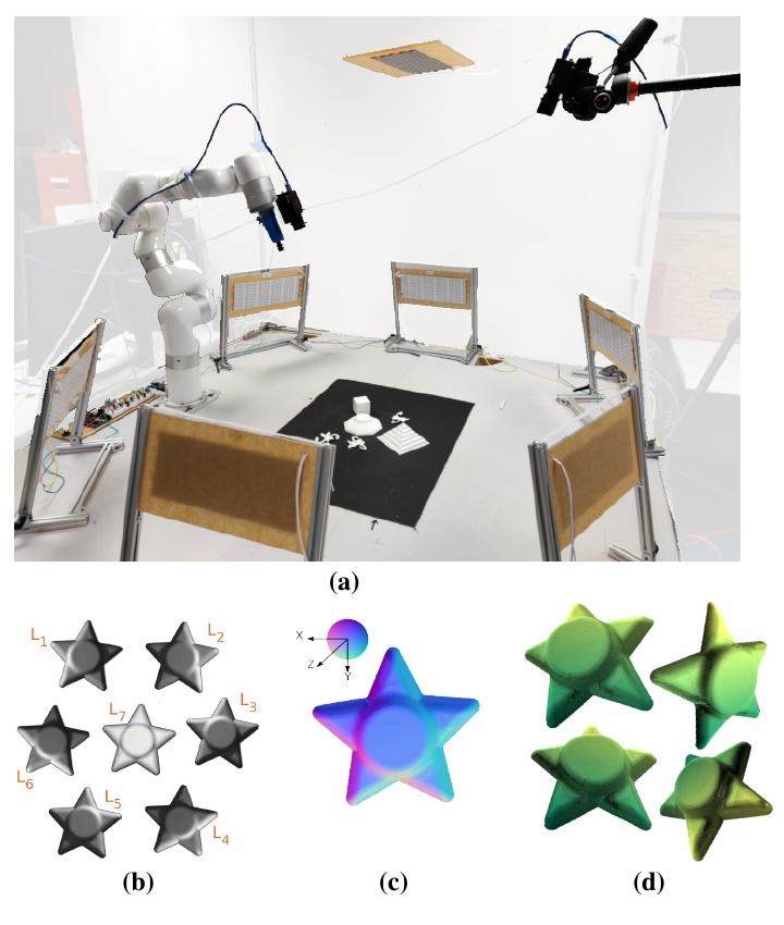
Workspace with two machine-vision cameras, six low-angle lights, one overhead light, and seven-image normal / surface outputs.
Table 2
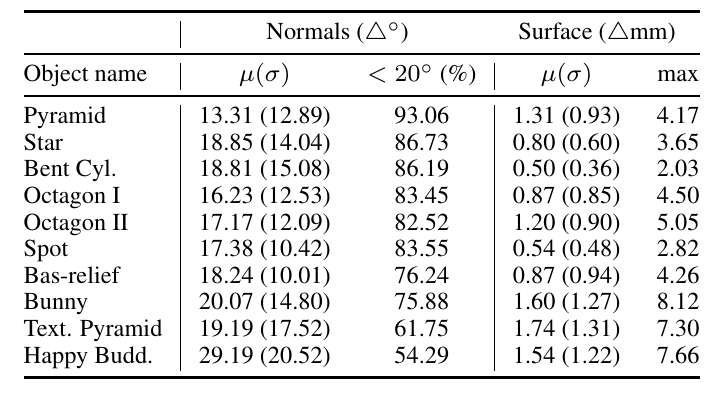
Normal-angle / integrated-surface errors on ten printed objects, bounding observation quality for downstream manipulation and pose.
Figure 5
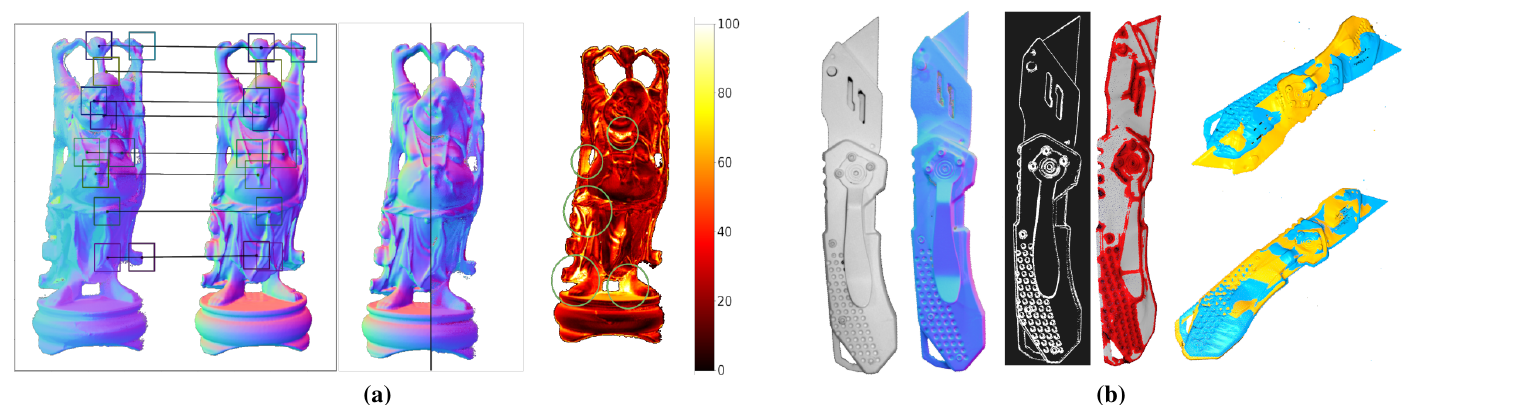
CAD-based normal-patch matching / render-and-compare at left; model-free registration of two observations at right.
Tables 4 / 5
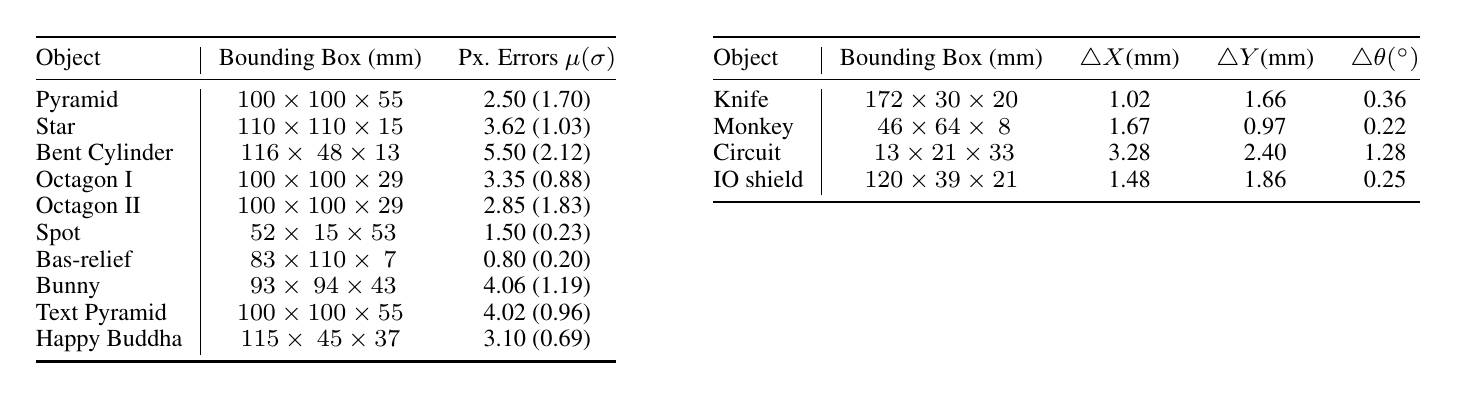
Known objects use image-edge pixel mismatch; unknown objects use planar ΔX,ΔY,Δθ. These do not form a unified 6D benchmark.
Original Figure 1: two cameras observe a tabletop illuminated by six surrounding low-angle lights and one overhead light. Seven captures yield photometric-stereo normals, optionally integrated into surfaces. Source: CVF Open Access. Image copyright belongs to the authors and publisher; reproduced here for paper analysis.
3. Problem setting
3.1 Observations and hardware
Two calibrated machine-vision cameras: robot-mounted C1 and fixed workspace camera C2;
Seven lights: six surrounding low-angle lights L1:6, plus overhead L7;
Seven sequential images of the same static object;
Controlled / calibrated camera poses, selected intrinsics, light directions, and illumination models.
3.2 Object assumptions
Mainly tabletop rigid objects smaller than about 20 cm;
Main experiments assume monochromatic Lambertian surfaces without substantial specularity;
Objects are sprayed matte white when necessary;
Near-complete visibility, controlled backgrounds, and stable illumination matter;
Known-object pose requires a 3D model; model-free cases estimate motion between observations of the same object.
3.3 Output levels
Output
Core contribution?
Description
Per-pixel normals
Yes
Invert linear / quadratic illumination models under six low-angle lights
Depth discontinuities / occlusion edges
Yes
Low-angle shadows highlight geometry
Integrated surfaces / point clouds
Optional
Integrate normals; unseen parts need not be metrically correct
Known-object pose
Application
Align measured normals, edges, and silhouettes to CAD renders
Unknown-object tracking
Application
Register two observed surfaces; main table tests planar x/y/θ only
4. Core motivation
Near-field stereo / ToF sensors may struggle with:
Small or thin objects;
Unstable correspondence on textureless surfaces;
Insufficient depth resolution for local normals;
Edge outliers, noise, and smoothing that obscure fine geometry.
Low-angle illumination makes tiny protrusions, creases, and depth discontinuities visible through shading / shadows. An actively imaged workspace lets inexpensive RGB cameras recover finer normals and edges than some commercial depth sensors.
The cost is constrained operation: objects must remain still for several illuminations, materials / environments need control, and hardware surrounds the table.
5. Method overview
5.1 Photometric stereo
For pixel k under light i, the linear Lambertian model is:
Iik=πρ⟨nk,li⟩,
A quadratic model uses second-order spherical harmonics:
Iik=nkTMink.
Measured intensities, known albedo, and per-channel li/Mi invert normals under the six low-angle lights, accounting for shadows. Spatial integration optionally yields depth / point clouds.
5.2 Known-object pose
Match local surface-normal patches between measured and rendered maps for initialization;
Optimize 3D model pose at multiple scales;
Compare normals, depth edges, and silhouettes jointly;
Assess image-space edge alignment.
5.3 Unknown-object tracking
Capture controlled lighting at two times for one object;
Estimate normals and depth edges;
Integrate view-specific point clouds;
Extract salient features and register rigidly;
Output relative pose change between observations.
Original Figure 5: 5a shows Happy Buddha normal-patch correspondences, measured / rendered overlays, and local costs; 5b shows model-free knife input, normals, depth edges, integrated points, and registration between observations. Source: CVF Open Access. Image copyright belongs to the authors and publisher; reproduced here for paper analysis.
6. Experimental overview
6.1 Normals and depth
Original Table 2: per-pixel normal angles and integrated-surface distances for ten printed objects. Simpler shapes have mean surface errors 0.50–1.31 mm; Bunny, Textured Pyramid, and Happy Buddha give 1.54–1.74 mm. Happy Buddha's mean normal error is 29.19°, showing substantial local-shadow / geometric failures. Source: CVF Open Access. Image copyright belongs to the authors and publisher; reproduced here for paper analysis.
Mean normal errors over ten objects: 13.31°–29.19°;
Pixels below 20° normal error: 54.29%–93.06%;
mean reconstructed-surface error: 0.50–1.74 mm;
max surface error: 2.03–8.12 mm.
Accurate overall surfaces do not imply accurate normals everywhere; pose optimization must tolerate local shadow outliers.
6.2 Commercial depth-sensor comparisons
Normal-distribution dissimilarity compares D455, D405, D435, L515, and Kinect II on flat / textured surfaces at frontal / 45° views. Interpret cautiously:
Textured-surface 0° / 45°: 0.18 / 0.10, with a smaller advantage;
Working distances, filtering, and acquisition differ; except D405, many devices target room scale. These are not fully matched product rankings.
6.3 Pose / tracking results
Original Tables 4 and 5: known-object results at left manually measure simulated / observed edge mismatch, averaging 0.80–5.50 px. Unknown-object results at right only measure relative planar $\Delta X$, $\Delta Y$, $\Delta\theta$, with maximum listed errors 3.28 mm, 2.40 mm, 1.28°. The original tables are cropped and juxtaposed for reading; data are unchanged. Source: CVF Open Access. Image copyright belongs to the authors and publisher; reproduced here for paper analysis.
Known objects: ten objects, five random poses each; about 7 px/mm resolution and mean edge mismatch 0.80–5.50 px.
No GT rotation / translation errors are reported. Good rendered overlays do not establish full 6DoF millimeter / degree accuracy.
Unknown objects: four objects, six known perturbations each; ΔX=1.02–3.28 mm, ΔY=0.97–2.40 mm, Δθ=0.22–1.28°.
The text summarizes roughly 4 mm translation / 2° planar-rotation uncertainty for relative planar tracking, rather than absolute unknown-object 6D pose.
6.4 Grasping and deformation
35 3D-object grasps plus 10 thin textured-object grasps yield four failures, all on the textured pyramid: suction attachment failure or triangulation-induced collision.
Buckling of 0.76 mm-thick, 86×54 mm PVC cards matches theoretical trends: fit R2=0.975, repeated cards / views R2=0.966.
These applications demonstrate useful normals / edges, without standard pose-benchmark validation.
7. Strengths and limitations
Strengths
Clear system design treats illumination as a controllable sensing variable.
Real grasping, thin objects, deformation, known pose, and unknown tracking go beyond offline image metrics.
Quantitative evidence covers surfaces, normals, image overlays, and planar tracking.
Joint normals / edges / silhouettes tolerate local errors; one pose example aligns despite about 50% of pixels exceeding 20° normal error.
Lambertian assumptions, visibility, view dependence, and non-Lambertian failures are discussed explicitly.
Seven sequential illuminations require near-static objects, restricting fast motion.
Workspace-scale light / camera calibration consumes space and is sensitive to ambient changes.
Known-object pose lacks standard R/t GT errors and mainstream pose baselines.
Unknown tracking tests only planar three-DoF motion; unseen surfaces / new views can invalidate integrated metric geometry.
Local normal errors exceed 20° and worsen for complex / self-occluding objects.
A generic-object extension uses PIE-Net and 30–40 lights, failing on glossy dark harvest and remaining far from main-system metric quality.
8. Research takeaways
Active perception: controlled illumination may be a direct route when workspace modification is possible.
Multimodal costs: combine reliable normals, silhouettes, and depth edges for refinement.
CAD-free tracking: direct same-view surface registration can outperform meshing noisy normal integrations.
Evaluation: image overlays and SE(3) errors are not interchangeable; preserve the paper’s actual metrics.
Baseline suitability: controlled near-field photometric stereo / active surface perception, with different assumptions from general passive RGB 6D pose.
9. Coarse-reading conclusion
Controlled illumination supplies high-resolution tabletop geometry useful for grasping, deformation, and pose. Known-model alignment and model-free tracking offer pose insights, with explicit boundaries: pixel-overlay evaluation for the former, relative planar motion for the latter, and strong dependence on matte Lambertian materials, static multi-light capture, and near-complete visibility.
Available src/paper-notes/shape-from-shading-manipulation-wacv2024/deep.md
In-depth paper notes
Support reproduction, comparison, related-work writing, and identifying opportunities for further research.
Deep Reading Notes: Shape From Shading for Robotic Manipulation
1. Basic information
Short name: Active Shape from Shading / Controlled-Illumination Workspace
Authors: Arkadeep Narayan Chaudhury, Leonid Keselman, Christopher G. Atkeson
Affiliation: The Robotics Institute, Carnegie Mellon University
Collection scope: extended inclusion. Active workspace shape sensing is the main task; pose / tracking is one of four downstream application groups.
2. Positioning in one sentence
Six low-angle lights and one overhead light turn a tabletop into a large photometric-stereo sensor. Two calibrated cameras observe static objects; illumination inversion recovers normals, shadows reveal depth discontinuities, and integration optionally produces local surfaces. Applications include suction grasping, thin-object detection, known-object deformation, CAD-based render-and-compare, and model-free relative planar tracking.
Three boundaries for pose readers
Known objects: complete 3D model pose may be optimized, but quantitative results report image-edge pixel mismatch without GT rotation / translation errors.
Unknown objects: relative registration between observations of one object, evaluating only planar ΔX,ΔY,Δθ rather than absolute pose.
Sensing assumptions: main experiments use monochromatic matte-white Lambertian surfaces, sprayed when necessary; unconstrained natural-RGB perception is outside scope.
Normal errors 13.31°–29.19°, mean surface errors 0.50–1.74 mm; accurate average surfaces do not imply accurate local normals
Figure 5
Pose / tracking
CAD-based multimodal comparisons; without CAD, register two integrated point clouds
Tables 4–5
Pose evidence
Known objects use pixels, unknown objects planar mm / degrees; do not combine them into unified 6D accuracy
Original Figure 1: robot-mounted C1 and fixed C2 observe sequential illumination from six low-angle lights L1:6 and overhead L7. Panels b, c, d show seven observations, photometric normals, and derived surfaces. Source: CVF Open Access. Image copyright belongs to the authors and publisher; reproduced here for paper analysis.
3. Problem setting and task boundaries
3.1 Beyond a single pose benchmark
The paper asks: can controlled illumination provide fine normals and depth discontinuities cheaply enough to support multiple tabletop manipulation tasks?
Experimental levels include:
Sensing quality: compare normals with commercial depth sensors;
Metric accuracy: measure normal / integrated-surface errors against printed known meshes;
Grasping: arbitrary 3D surfaces and thin flat objects;
4.1 From passive perception to active illumination
Ordinary RGB-D treats lighting as environment; this system controls it as an action. Active perception can control:
environment: illumination;
extrinsics: camera position / pose;
Intrinsics such as gain / focal length.
The paper chiefly controls the first variable, alongside fixed / robot-mounted cameras. It changes imaging physics to strengthen geometric pixel signals before inference.
4.2 Relationship to photometric stereo
Classical photometric stereo infers normals from intensity changes under fixed cameras and varying light directions. Contributions adapt this to robotics:
Workspace-scale calibration of linear / quadratic illumination models;
Six low-angle lights exposing local geometry / depth discontinuities;
Explicit shadow handling;
Normals / edges connected to manipulation and pose;
Near-field normal-quality comparisons with commercial depth sensors.
4.3 Differences from learned 6D pose
Dimension
This system
Typical RGB / RGB-D pose network
Data
Seven actively illuminated captures
Natural single images or video
Features
Calibrated photometric normals + edges
Learned RGB / depth features
Appearance
Mainly white-painted Lambertian surfaces
Attempts natural textures / materials
known pose
analysis-by-synthesis optimization
direct / keypoint / correspondence + solver
Unknown pose
Two-time local-surface registration
Novel-object reference matching / reconstruction
Evaluation
Pixels or planar x/y/θ
ADD(-S), BOP AR, R/t errors
This is active geometric sensing plus classical alignment, with different assumptions from FoundationPose / MegaPose baselines.
5. Research motivation
5.1 RGB-D challenges for small, thin, weakly textured objects
At tabletop scale:
Stereo needs texture / projected patterns;
ToF / structured-light resolution and edge noise can obscure millimeter structures;
Temporal / spatial smoothing weakens curvature and sharp edges;
Commercial depth sensors may miss a 3.15 mm-thick disc.
5.2 Why low-angle illumination helps
Fine surface discontinuities cast visible small shadows;
Mi is the per-light quadratic model. Inference uses per-channel linear / quadratic calibrations, sequentially inverting normals under L1:6 and handling shadows. Full details are in the supplement.
Color texture edges, with different locations / responses across lights;
Geometric occlusion edges, with stable shadow cues along light directions.
The thin disc cannot be separated from table texture under overhead light alone. Low-angle shadows reveal its edges; C1 / C2 minimum-enclosing circles triangulate its center.
6.4 Normal integration
Normal integration supplies view-specific depth / points, scaled with intrinsics. Errors accumulate and unseen parts lack metric geometry. Meshing these points for CAD-based pose later performs worse than directly registering observed point clouds.
7. Method II: known-object pose
7.1 Pipeline
Estimate measured normals NR, depth edges, and silhouette MR;
Render candidate-pose normals NS, edges, and silhouette MS;
Match local normal patches for initial poses;
Optimize at multiple scales;
Combine normal, edge, and silhouette mismatches;
Retain / converge to poses best explaining observations.
Original Figure 5: 5a links measured / rendered normal patches, overlays $N_R/N_S$, and displays per-pixel costs; 5b shows a model-free knife's image, normals, edges, integrated features, and initial / final registration. Source: CVF Open Access. Image copyright belongs to the authors and publisher; reproduced here for paper analysis.
7.2 Why multimodal costs tolerate errors
About 50% of Happy Buddha pixels exceed 20° measured-normal error, with high costs around undercuts. Boundaries and other patches still constrain pose. Modalities complement each other:
The authors report convergence within 5.5 px for ten objects, within this controlled workspace and image-overlay protocol.
7.3 Evaluation protocol
C1 field of view: 227 mm × 129 mm;
Resolution: about 7 pixels/mm;
Random positions / orientations per object;
Overlay simulated and measured data after alignment;
Manually measure edge pixel mismatch;
Repeat 5 times per object;
Report means / standard deviations.
No mocap / calibrated-turntable GT R,t is supplied. Table 4 cannot yield rotation degrees, translation millimeters, or ADD(-S).
8. Method III: model-free relative tracking
8.1 Redefining the problem
Without CAD or a canonical object frame, classical absolute pose from one observation is ill-defined. Instead, estimate pose change between two observations of the same object.
8.2 Pipeline
Capture multi-light images at two times;
Estimate normals / depth edges;
Integrate view-dependent points using intrinsics;
Extract salient point features;
Register point clouds rigidly;
Recover relative ΔX,ΔY,Δθ.
8.3 Why this is not arbitrary 6DoF tracking
Table 5 has three error columns:
ΔX;
ΔY;
Δθ.
No quantitative ΔZ, roll, or pitch results appear. The text summarizes about 2° planar rotation and 4 mm translation, so these notes call it relative planar tracking. Registration could extend to 6DoF, but evidence does not establish these errors across all six freedoms.
8.4 View-dependent geometry
Integrated unseen surfaces are explicitly not metrically correct, such as knife belt-clip sides. With sufficient overlap, relative depth and scale support registration; new views / large rotations undermine this condition.
9. Surface-sensing experiments
9.1 Commercial depth-sensor comparisons
Objects / conditions:
Flat and textured surfaces;
Frontal optical-axis and 45° views;
D455, D405, D435 stereo;
L515, Kinect II ToF;
Ours photometric stereo.
For depth sensors:
Stereo: 50 frames per pixel, discard the top / bottom 10% and average; capture takes 1.5–2 s;
Project visible / infrared patterns on textureless surfaces as recommended;
Comparison limits: active sensing uses a dedicated near-field workspace, material priors, and multiple captures; most commercial devices target room scale. Results support superior normals in this setting, rather than universal sensor superiority.
9.2 Printed-object metric accuracy
Original Table 2: normal columns give angular mean(std) and fractions below 20°; surface columns measure integrated-surface distance to GT meshes in mm. Happy Buddha has mean normal error 29.19°, only 54.29% below 20°, yet mean surface error 1.54 mm. Local normals and global integrated alignment are different quantities. Source: CVF Open Access. Image copyright belongs to the authors and publisher; reproduced here for paper analysis.
Object
Normal mean(std)
Pixels <20°
Surface mean(std)
Surface max
Pyramid
13.31° (12.89°)
93.06%
1.31 (0.93) mm
4.17 mm
Star
18.85° (14.04°)
86.73%
0.80 (0.60) mm
3.65 mm
Bent Cylinder
18.81° (15.08°)
86.19%
0.50 (0.36) mm
2.03 mm
Octagon I
16.23° (12.53°)
83.45%
0.87 (0.85) mm
4.50 mm
Octagon II
17.17° (12.09°)
82.52%
1.20 (0.90) mm
5.05 mm
Spot
17.38° (10.42°)
83.55%
0.54 (0.48) mm
2.82 mm
Bas-relief
18.24° (10.01°)
76.24%
0.87 (0.94) mm
4.26 mm
Bunny
20.07° (14.80°)
75.88%
1.60 (1.27) mm
8.12 mm
Textured Pyramid
19.19° (17.52°)
61.75%
1.74 (1.31) mm
7.30 mm
Happy Buddha
29.19° (20.52°)
54.29%
1.54 (1.22) mm
7.66 mm
Undercuts, self-shadows, and textures worsen local normals. Pose needs robust multipatch / multimodal fitting rather than treating every normal as precise.
10. Manipulation and deformation
10.1 Suction grasping
For ordinary 3D objects:
Find locally flat regions large enough for the cup;
Exclude occlusion edges;
C1 / C2 triangulate world point;
Orient the gripper using local mean normals;
Approach and grasp along minimum-jerk trajectories.
Only vision is used, without force / torque inputs. Near-complete two-view visibility is required. Initial-mesh analysis by synthesis is more reliable than direct surface reconstruction because normal integration depends strongly on viewpoints.
11. Quantitative pose / tracking
Original Table 4 at left gives five-trial edge pixel mismatch mean(std), without GT $R/t$ errors. Table 5 at right gives planar translation / rotation errors under six known perturbations. Original tables are cropped side by side without redrawing or modifying data. Source: CVF Open Access. Image copyright belongs to the authors and publisher; reproduced here for paper analysis.
11.1 Known-object edge alignment
Object
Bounding box
Pixel error mean(std)
Pyramid
100×100×55 mm
2.50 (1.70) px
Star
110×110×15 mm
3.62 (1.03) px
Bent Cylinder
116×48×13 mm
5.50 (2.12) px
Octagon I
100×100×29 mm
3.35 (0.88) px
Octagon II
100×100×29 mm
2.85 (1.83) px
Spot
52×15×53 mm
1.50 (0.23) px
Bas-relief
83×110×7 mm
0.80 (0.20) px
Bunny
93×94×43 mm
4.06 (1.19) px
Textured Pyramid
100×100×55 mm
4.02 (0.96) px
Happy Buddha
115×45×37 mm
3.10 (0.69) px
At roughly 7 px/mm, 0.8–5.5 px corresponds approximately to 0.11–0.79 mm of projected edge mismatch, not object-frame translation. Projection mixes depth, rotation, translation, intrinsics, and edge choices; dividing by 7 does not establish 6D translation accuracy.
11.2 Unknown-object planar tracking
Object
Bounding box
ΔX
ΔY
Δθ
Knife
172×30×20 mm
1.02 mm
1.66 mm
0.36°
Monkey
46×64×8 mm
1.67 mm
0.97 mm
0.22°
Circuit
13×21×33 mm
3.28 mm
2.40 mm
1.28°
IO shield
120×39×21 mm
1.48 mm
1.86 mm
0.25°
The text’s approximate 4 mm translation / 2° planar uncertainty is more conservative than table maxima. Four objects have six repetitions each, without standard deviations, confidence intervals, or breakdowns for large rotations, low overlap, depth changes, and occlusion.
12. Generic-object extension
The main system assumes matte-white Lambertian objects. The extension:
Uses pretrained PIE-Net for intrinsic-image decomposition;
Splits natural RGB into reflectance and shading;
Applies global linear photometric stereo to shading images;
Selects 30–40 directions from DiLiGenT’s 95 lighting conditions;
Shadows / specularities are not explicitly handled;
Metric quality remains far from the main robot setup, as the authors acknowledge.
This is a possible extension, without eliminating material priors.
13. Robustness and failures
13.1 Shadow ambiguity
Low-angle shadows reveal depth edges but can break local normal inversion. Complex edges / undercuts exceed 20° local errors; the authors suggest non-colocated lights and cameras as one cause.
13.2 Specularity / color texture
Main experiments remove texture through white paint;
Sensor-comparison advantages shrink on textured surfaces;
The generic extension fails on glossy dark harvest.
Natural reflective, transparent, or colored objects therefore remain unresolved.
Model-free registration depends on temporal surface overlap;
Skewed views reduce shared pixels and worsen deformation estimates.
13.4 Motion
Seven lights are captured sequentially. Object / arm motion mixes illumination with motion-induced intensity changes, violating classical photometric stereo. Dynamic capture FPS and motion compensation are unreported.
13.5 Grasp failures
Four textured-pyramid failures arise from:
Unstable suction attachment;
Triangulation errors causing collisions.
Good normals / edges alone cannot guarantee successful end-effector mechanics and calibration throughout the pipeline.
13.6 Representation failure
Meshing unknown-object integrated points and feeding them to the known-object pipeline performs worse. Normal estimation, integration, and meshing accumulate errors, and view-dependent meshes fail metrically from new views. This is a valuable negative result.
14. How well do experiments support contributions?
Authors’ claim
Evidence
Support
Assessment
High-quality normals / edges from controlled light
Tables 1, 2; Figure 2
Substantial
Effective near-field controlled sensing; complex-object local errors remain high
Better than commercial depth sensors
Table 1
Partial
Best on this near-field normal metric, with differing device ranges / conditions
Supports general suction grasping
45 trials, 4 failures
Partial
Real robots, but few objects and no baseline / confidence intervals
Measures known-object deformation
Figure 4, Table 3, R2
Substantial
Reproduces buckling with mesh / visibility assumptions
Estimates known-object poses
Figure 5a, Table 4
Partial
Small overlays, without GT R/t or pose baselines
Tracks unknown objects
Figure 5b, Table 5
Partial
Four-object planar tests, without full 6DoF / large-view validation
Extends to generic materials
Figure 6
Weak
Qualitative proof of concept; glossy dark failures, 30–40 lights
15. Critical analysis
15.1 Strengths
Improve physics-level observability: illumination design strengthens evidence before learned priors.
Full-system evidence: calibration / sensing connect to real grasps, poses, and deformation.
Match metrics to claims: pixel overlays support alignment, without establishing metric 6D accuracy.
When to cite this in related work
active perception / active illumination;
photometric stereo for manipulation;
suction grasp surface-normal estimation;
analysis-by-synthesis known-object pose;
model-free relative object tracking;
small / thin object sensing.
Potential research entry point
Build uncertainty-aware RGB-D + coded-light pose refinement: a foundation model supplies masks / coarse poses, then 2–3 informative lighting directions support predicted normals, shadow confidence, and depth-edge corrections. Symmetry-aware render-and-compare outputs pose covariance, evaluated with standard BOP and robot-grasp protocols.
19. Open questions
Conceptual questions
How does 3D uncertainty vary with depth / object size for equal edge errors?
When are low-angle shadows useful edges versus normal-inversion outliers?
Do normal-patch descriptors yield multimodal matches on symmetric geometry?
Formula / implementation questions
Combining linear / quadratic inversion and sequential solvers;
Shadow thresholds and per-channel calibration;
Integration boundaries and metric scale recovery;
Multimodal weights, pyramid levels, and optimizers;
Model-free point features and robust registration.
Errors versus natural albedo, roughness, and metallicity without paint;
Tracking failure thresholds as C1 / C2 overlap falls.
Reproduction questions
Completeness of public code / hardware bills;
Light models, distances, angles, and intensities;
two-camera synchronization;
Alignment between painted CAD objects and GT meshes;
Matched distances, FOVs, and resolutions in sensor comparisons.
20. Final assessment
Authors’ claim
Workspace-scale controlled lighting yields fine normals and depth discontinuities cheaply, outperforming several commercial depth sensors for small tabletop objects and supporting suction grasps, deformation, known-object pose, and model-free tracking.
My analysis
Evidence supports controlled matte-Lambertian small-object sensing and manipulation utility: mean surface errors 0.50–1.74 mm, ten known-object edge errors 0.80–5.50 px, four unknown-object planar table errors at most 3.28 mm / 2.40 mm / 1.28°, plus 45 real grasps and PVC deformation.
Pose claims require limits: known-object tables lack GT R/t, and unknown-object tests cover only x/y/θ, not generic 4 mm / 2° full-6D accuracy. White paint, static seven-light capture, calibration, and high visibility remain prerequisites. The transferable lesson is design illumination / observation when passive images cannot reveal fine geometry, then use physically interpretable normals / edges for pose and manipulation.